


Parts List
- (1) Tap-Tempo Metronome Printed Circuit Board – PCB
- (1) 3xAAA Battery Holder – BT1 (unlabeled)
- (1) PIC16F685 Microcontroller – U1
- (1) .3″ 20 Pin DIP Socket – U1
- (3) 0.3″ Seven Segment LED Displays – AFF1, AFF2, AFF3 (unlabeled)
- (2) Push Buttons – SW2, SW3
- (1) Power Switch – SW1
- (3) NPN Transistors – Q1, Q2, Q3
- (1) .10 uF Ceramic Capacitor – C2
- (1) Piezo Speaker – SP1
- (1) Power Protection Diode – D1
- (1) 10 kΩ resistor – R1

What does each part do?
There’s more information about the design of the Tap-Tempo Metronome kit at the Design page.
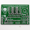
Tap-Tempo Metronome PCB (Back to list)
A professionally-made PCB is the key to many successful projects. The PCB is a fully-custom design with two signal layers and no vias. All parts are through-hole for easy soldering, with full soldermask and complete silk-screen labeling of all parts.
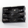
The battery holder holds the batteries and connects them together to the rest of the circuit.
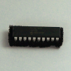
The PIC 16F685 is a re-programmable microcontroller used to coordinate the rest of the Tap-Tempo Metronome. It runs firmware written in the C programming language. There is a more detailed explanation of the firmware at Firmware Design Explanations.
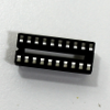
The socket is a way to connect the chip to the PCB without soldering the chip directly. By soldering the socket on the board instead, there’s no possibility of overheating the chip with the soldering iron. The chip can also be removed or replaced without soldering.
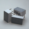
Seven Segment LED Display (Back to list)
The seven segment LED display is used to display the beats per minute on the metronome. These are common anode displays. This means that on each display, each LED (segment) is connected together at the power side and connected to an individual pin on the ground side. To make a segment glow, a voltage is applied to the common anode pin, and a lower voltage is applied to the segment pin.
A resistor is commonly used when powering LEDs. This is to avoid damaging the LED. However, many LEDs can be powered without resistors if the power is pulsed. This puts the “average” power within safe limits and the LED isn’t damaged. The appropriate information can usually be found on the LED datasheet.
This pulsing technique is used to eliminate the need for the resistors. Transistors are used to multiplex the display so fewer pins are required to display all three digits. For more information about multiplexing LED displays, please check out our design documentation.
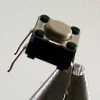
The push buttons are used to provide input to the microcontroller. In this application, they’re used to change the tempo of the rhythm.
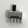
The power switch is used to control the power to the circuit.
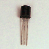
NPN Transistors (Back to list)
The NPN transistors are used to enable and disable each digit of the seven segment LED displays.
The human eye is much slower than a microcontroller and an LED. If the LEDs are switched on and off quickly, we don’t perceive the gaps, just like we see fluid motion when watching a movie made from still frames. We can use this to our advantage to reduce the pin count required to connect all the seven segment LED displays to the microcontroller. If we use the transistors to switch the seven segment displays on and off, we can make sure only one display is on at a time. Once we have this guarantee, we can join all the similar segments together and connect all three similar segments to the microcontroller with just one pin per segment. For example, all the top-most segment pins would be connected to each other, and connected to only one pin on the microcontroller. We need one pin per digit for the transistor to turn the digit on or off. After that, we just need 7 pins to control the segments, and we have full control over the whole display. This takes a total of 10 pins, compared to at least 21 pins if each segment was directly driven by a microcontroller pin. For more information about multiplexing LED displays, please check out our design documentation.
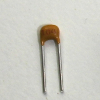
.10 uF Ceramic Capacitor (Back to list)
The .10 uF ceramic capacitor is used to smooth the power supply. When the power switch is used, the voltage can “get a little jumpy.” By adding a capacitor, this jumpiness is reduced. When the circuit is first turned on, the capacitor charge-up and smooth that transition. When the circuit is turned off, the capacitor discharges and smooth that transition as well.
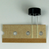
The piezo speaker is used as both input and output in the Tap-Tempo Metronome. It does the beeping in the circuit as well as senses the taps. When the circuit beeps, it’s due to the microcontroller applying a square wave of 0 and 5 volts across the leads of the piezo speaker.
The piezo speaker contains a tiny piece of ceramic that exhibits the piezoelectric effect. This means that when the ceramic is flexed, it generates a voltage, and when a voltage is applied across it, the ceramic flexes. This crystal is attached to leads and placed inside a small plastic resonant chamber. This resonant chamber makes the sound louder.
This piezo speaker is direct-drive, which means that something outside of the speaker has to generate the frequency that the piezo will buzz at. Self-driven piezo speakers have some circuitry in them that lets them buzz themselves when powered. For more information about doing input and output with a piezo element, please check out our design documentation.
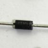
Power Protection Diode (Back to list)
To protect the circuit against backwards batteries / power connections, a diode is placed in-line with the power supply voltage. A diode is a polarized circuit component that only passes electricity in one direction. This diode will only conduct electricity when the batteries are connected correctly. If the batteries are put in backwards, the diode will not conduct, protecting the circuit from the reversed voltage. The diode is a polarized part, meaning that it must be inserted the correct way. Match the silver stripe on one end of the diode with the heavy white line on D1 on the PCB, the side with the square pad.
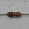
10k Ohm 1/4W Resistor (Back to list)
The resistor in the circuit is used to provide a path from the piezo speaker to ground. Without it, when the piezo is tapped, charge builds up on the element and readings become inaccurate. The resistor provides a path to ground for that charge.