


Design
Design Documentation
This page has more details about the design of the Tap-Tempo Metronome. Other formats for the schematic, layout, and Kicad design files are available at the download page.
Layout

Schematic

Firmware Design Explanations
The source code is thoroughly commented in-line, but a few of the concepts merit further explanation:
- Seven Segment Display Multiplexing
- Software-based Button Debounce
- Piezo Input and Output
- Pattern Detection
- External Connections
If there is any aspect of the hardware or firmware that you’d like to be explained in more detail, please let us know. Thanks!
Seven Segment Display Multiplexing – This technique is used to reduce the number of pins required to control the three displays. A seven segment display has one pin for each of the segments, and at least one pin that is in common. Our displays are common-anode, meaning that the anodes of all the LED segments are connected together. When an individual segment’s pin is connected to ground through a resistor, that segment lights up. We connect all of the common segment pins, A through G plus DP, together to the microcontroller. We then use a Bipolar-Junction Transistor (BTJ) to turn on and off each segment individually, using a control signal from the microcontroller. In this way, we can control each digit individually.
 Just like how a movie projector showing a rapidly-changing sequence of still images appears to be smooth motion, “persistence of vision” can be exploited here with the LED seven segments. By turning the individual digits on and off rapidly, we can give the appearance that all three digits are active at the same time. This method of multiplexing also allows us to fine-tune the brightness of the LEDs, which lets us get away without current-limiting resistors on each LED segment. For more information about running an LED without a resistor, check out this great guide at the Tinkerlog website. Basically, we ensure that each digit is on for only a short period, to avoid burning it out.

In the image above, we have plotted the digit enable signals for each digit with respect of time. For example, if we look at the D0 signal, we see that near the start (left side) the digit is briefly enabled, and then turns off. After a wait time, the next digit, D1, is enabled, followed by another wait time, and then D2 is enabled. After a final wait time, the process repeats endlessly. In the picture below, the metronome is being shaken up and down. The camera’s shutter is open long enough to capture a bunch of digits being turned on and off. Since the metronome is moving, the digits appear in different places, making it easy to see the individual digits switching on and off. Click on the picture for a higher resolution image.

The on and off times are configurable in the source code, which allows us to control the apparent brightness of the displays. One useful application of this control is the flashing of digits on each beep. When a beep is being produced (about 20 milliseconds long), the wait time is reduced, making each digit on for a greater percentage of time, appearing brighter than normal.
Software-based Button Debounce – The push buttons in the Tap-Tempo Metronome are each connected to an input pin, allowing the buttons to signal the microcontroller. The circuit is laid-out such that the pins are normally at logic high, and pressing the button connects the pin to ground. While we might like to think of buttons as ideal or perfect, noise-free devices, this is unfortunately not the case. Every time we push a button, there is a period of electro-mechanical noise, due to the button’s contacts scraping and bouncing against each other. When we flick a light switch, this bouncing is so fast that our eyes can’t see it, but a microcontroller is running much, much faster, and must deal with this undesired noise.
 In the graphic above, we see how pressing and holding the push button creates a signal that bounces around, back and forth, between logic high (sampled value of 1) and logic low (sampled value of 0). If we were to write our firmware code without considering the button’s bounce, each button press would likely trigger many changes! In order to safely detect each unique button press, we need to write better code to sample the pin’s value over time. In the example above, we only consider the button pressed when we observe four consecutive samples of logic low. We keep track of the state of each button, and only update it when a sufficient number of consecutive values is observed. In the Tap-Tempo Metronome firmware, we actually require 8 consecutive identical samples before acknowledging a button push or release.
Piezo Input and Output – Whether entering a new beat pattern or listening to the metronome beeps, a piezo-electric element is involved. The piezoelectric effect is a property of some materials to generate an electric charge in response to mechanical stress, and also to generate physical deformation in response to an electric field. We can exploit these properties to detect when the piezo is tapped, and produce a loud chirping beep using the same piezo.
To product a beep sound on the piezo, we need to drive a square wave across the outputs of the piezo element. The piezo in the Tap-Tempo Metronome has a package with a resonant frequency of 4 kilohertz (khz), so we want to create a square wave with that frequency to get the loudest sound output. We use Timer 2 on the PIC 16F685 to drive the pulse-width modulation output with a 50% duty cycle. Timer 2 has a configurable prescaler, which we set to 4:1. This means that one output clock is produced for every four input clocks. Using the equation from the datasheet we find that we need to set the period register for Timer 2 (PR2) to be 124 to produce a 4khz output square wave:
PWM period = (PR2 + 1) * 4 * Tosc * TMR2_prescaler 1/4000 = 0.00025 = (124 + 1) * 4 * 1/8MHz * 4 |
To read input taps on the piezo, we need to use the PIC’s Analog-to-Digital converter (ADC) to sample the voltage of the piezo. When the piezo is tapped, it will generate a ringing voltage spike on the ADC input pin, as seen in the image below. When we are not actively driving the piezo with a square wave, we are continually sampling the ADC input pin, looking for a voltage above the threshold voltage. Currently, the threshold voltage is 200 / 1024, which is about 20% of the supply voltage. With three fresh AAA batteries, the threshold voltage is about 0.87 volts.

Once we detect a voltage above the threshold, we record the time of the tap, and enter a 30 milliseconds timeout period where we ignore any further taps. This helps to solve a problem similar to the button debounce problem above, but here we solve it simply by waiting for 30 ms. We have a 10k resistor across the piezo, which is used to drain away the excess charge generated by tapping the piezo. This piezo input circuit was inspired by the circuit in Todbot’s “Arduino MIDI Drum Kit” article. We decided not to include the 5.1v zener diode for chip protection as the PIC microcontroller has built-in, internal protection diodes on each input pin.
Pattern Detection – When the user enters a sequence of taps, the pattern detection software must analyze the sequence and determine how long the pattern is, and characterize the tapping pattern. To do this, we will look at the sample tap sequence below, consisting of nine taps. It is important to notice that while there are nine taps, there are only eight intervals, and we will be recording the durations of these intervals.

Although we can easily see that there are three repetitions of a pattern of length three, for the microcontroller to figure it out takes more work. The basic idea is to compare each occurrence of a beat across all measures, and compute a total penalty or “cost” difference between beats that should be the same length. For the example above with eight intervals, the pattern detection code first finds the cost for a pattern of length 1, then finds the costs for patterns of length 2 and 3. For example, when finding the cost for a pattern length of 3, it would compare intervals 0, 3, 6 to see how much they differ, then intervals 1, 4, 7, then intervals 2, 5. The lowest cost should be associated with the best-fit pattern length. Here, the best pattern length is three. Take a look at the first half of the source code function do_pattern_recognition() for more details on finding the best-fit pattern length.
Once we have determined the length of the pattern, we go through and average-out all the occurrences of each beat, to get a more accurate interval for playback. For our example above with pattern length of three, we take the mean of intervals 0, 3, and 6 to find the average length of the first beat. Since we are basically “distilling” down all the interval values into one measure of intervals, we can simply overwrite the value in interval 0, since we will not need the original value in the future. We do the same for the rest of the intervals in the pattern, overwriting intervals 1 and 2 in the process, in the blue box below.

Once we have computed the mean interval for each beat, we are ready to begin playback. We start by playing a beep and waiting the proper time, stored in the first measure of the intervals[] array. If the user uses the up and down buttons to adjust the pattern frequency, we store scaled copies of the mean interval values in the next measure of memory in the intervals[] array, denoted by the purple box above. In the example above, we have scaled the original intervals by 1.5, leading to a 50% slow-down in pattern playback. We decided to store a scaled copy of the intervals instead of overwriting the intervals in order to increase the accuracy of the playback, and to avoid scaling/roundoff errors when repeatedly multiplying and dividing the interval values.
External Connections
One of the features we wanted to add when re-designing the original metronome kit was to make it much easier for people to hack the kit, and add external connections. To this end, we added six header pin connections at the bottom of the circuit board:
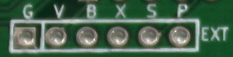
Here’s an explanation of what each of those pins is doing:
- Pin G – This pin is the ground connection, tied to the negative terminal of the battery holder. All signals are voltages measured relative to this ground.
- Pin V – This pin is the voltage connection, tied to the positive terminal of the battery holder when the power switch is in the “on” position. This can be useful if you want to draw a bit of voltage to power your external hardware.
- Pin B – This pin is the beat connection. The pin goes high (is equal to the V pin’s voltage) whenever the kit is beeping (for the duration of each beep). It outputs a solid (non-PWM) signal. This signal might be useful to trigger external lights or motors or sequencers or synthesizers, etc.
- Pin A – This pin is a spare GPIO pin on the microcontroller, specifically it’s pin 3 named RA4. We didn’t have anything to use it for, but we added it to this header in case you want to hack the firmware to do something cool with it.
- Pin S – This pin is the synchronize pin, which could someday be useful for connecting multiple metronomes together with a common timebase. We didn’t end up creating a way for you to connect multiple metronomes, but we thought it would be pretty cool to set one metronome going, then use the sync pins to allow the other metronomes to keep in sync with the “master” metronome started first. As it is, this pin is similar to the A pin, it’s just connected to a GPIO pin on the microcontroller, specifically it’s pin 12 named RB5.
- Pin P – This pin is the PWM output from the microcontroller that is used to drive the on-board piezo buzzer. If you want to make an external piezo beep, this is the pin for you, just connect the piezo between pin P and pin G (ground) and it should beep. The output signal is a 4 kHz square wave whenever the kit is beeping. If you want to disable the on-board piezo from beeping, check out the instructions here for which trace to cut.
Here’s a graphical explanation of the difference between the B “beat” and P “pwm_out” signals:
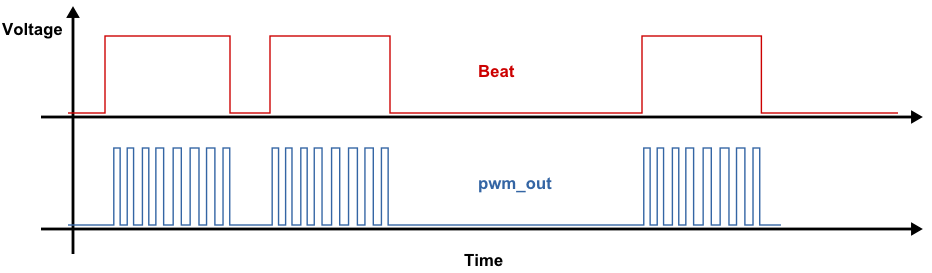
(Click image to enlarge.)
There are some more photos and information about external connections in the W&L Discussion forum.