


Beta test for Wayne and Layne!
Free hardware!
We’re looking at producing some of our upcoming kits in vast vast numbers (for us), and to reduce our risk, we want to get the hardware in a bunch of people’s hands to see what they think.
We hope to send out some hardware to folks within a few weeks, have them build our kit, play with it for a little bit, and then have them give us some feedback.
The kits are blinky and awesome, and should take less than an hour to assemble and less than half an hour to play with.
To do so, we made a little form for folks to apply. Don’t feel intimidated by the questions–we’re looking for a wide batch of folks, not just the ones with the most experience.
We’re looking to make our decisions soon, so don’t delay! The form shouldn’t take more than a few minutes to fill out.
We recently received quite a lot of requests for a video game that doesn’t need Wii controllers. This afternoon I took ten minutes and adapted our popular two-player PONG game to use two potentiometers as controllers, instead of the Wii Nunchucks. The potentiometers will be connected to the Arduino’s analog inputs 0 and 1.

I used two trimmer-style potentiometers mounted in a breadboard. These potentiometers have three leads, and the center lead is commonly called “the wiper”. Connect the other two pins to 5v and Ground, and connect the wiper to analog 0 / analog 1. As the potentiometer is turned, the wiper will have a voltage between 0 and 5 volts, which is measured by the Arduino’s analog inputs 0 and 1. These measured analog voltages are then digitized and used to position each player’s paddle.

The new sketch, tv_2p_pong_potentiometers, is now available in our regular library zip, as well as on github.
Arduino Tetris on the Video Game Shield
Myles recently ported an open Tetris clone to the Arduino. We added support for the Nunchuck (so now it works with both the Nunchuck and the Classic Controller) as well as music!
It’s available in our regular library zip, as well as on github.
Buy the Video Game Shield add-on for the Arduino for $22.50 in the Wayne and Layne store today!

I noticed this video by MisterReplicant a few days ago. It’s entitled Arduino Video Game Shield/Christmas Stuff, and a large portion of the video is him showing a constructed Video Game Shield.
We’ve sold hundreds and hundreds of Video Game Shields over the last few months, helping people use their Arduino to make video games, control their television, or take Wii controller input. Why don’t you take a picture or write up a little description of what you’ve done, and send it our way! We’ve got forums, but we’ll also gladly link to your video or writeup somewhere else.
Happy New Year!
2010 was quite an eventful year here at Wayne and Layne–but here’s hoping for double the nerdery in 2011!
We’ve had an implementation of Conway’s Game of Life on the Video Game Shield since day one, and we’re pretty proud of it. It’s got just about all the features we want. It’s controllable by a Wii controller which lets you pause or single step through the cellular automata. We also have a menu system, where you can randomise the field, or load a saved pattern out of the flash memory. It comes with 7 patterns already built in.
Today, we’re releasing an open source webapp (and some Python CLI stuff) called Lifeconvert that lets you take a Life 1.06 file and convert it to be copy-and-pastable into the Arduino sketch, in order to add your own patterns to the program.
If you wanted a turn-key Game of Life to display on anything that takes NTSC or PAL input, the Video Game Shield is it!
How to put custom patterns into the Video Game Shield Game of Life Arduino Sketch
What we’re going to do is take a Life 1.06 file, convert it through http://lifeconvert.wayneandlayne.com into the form of our Pattern struct, paste it into the right place in Patterns.h of our tv_life sketch, and then update the patterns[] array to point to the struct we just added.
Go to http://liveconvert.wayneandlayne.com. Upload a new pattern or use an example. You can also find plenty of Life 1.06 files in the LifeWiki’s Pattern category. They’re usually available for download in the sidebox of a given pattern article.

The website draws the pattern, and puts the converted struct data at the bottom.

Copy everything after the image.
Start the Arduino program on your computer. Open up tv_life from the VideoGameHelpers example directory. Save it with a new name, maybe in your sketchbook. This way, when you make changes, if you mess something up, or just want to go back to the original, you can go back to the examples and the original will be there.
Go to the Patterns.h tab.

The file will be pretty long! If you scroll down, you’ll notice that the bulk of the file is comments and structs. These structs are the life pattern data, and they’re stored in Flash memory. They don’t use up your RAM, which is limited to 2kB on most Arduinos (the ‘328 ones), but instead are stored in the program memory, which is limited to around 30kB on the Arduinos that use the ‘328 chip.
To replace one of the built-in patterns with your own, click below the line that says
#define NUM_OF_PATTERNS 7
and paste your clipboard. You should see a bunch of new stuff, which is what you copied from the Lifeconvert web page.
At the top of what you pasted in, you should see a line like
const Pattern big_s PROGMEM = {
The part “big_s” is the name, and it should be related to the pattern name you put into the lifeconvert site.
Scroll down to the bottom of the Patterns.h file.

Edit patterns[] array to have the name of your pattern in it. Make sure to make it look like the rest of the array, with the (const Pattern*) &. Remove one of the patterns you don’t want to keep, and you’re done!
Upload to your board. Press the C button to enter the menu, scroll to “Load Saved Pattern”, and the name of your pattern should show up! Select it, and sit back and enjoy.
As always, we’d like to hear any comments, concerns, rants, or ransom demands you may have.
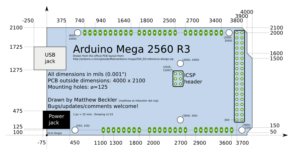
If you’re looking to make your own shield for the Arduino platform, you’ll definitely need to know where all the pins and holes are located on the Arduino. After doing a quick search, I was unable to find an accurate technical drawing of the new Arduino UNO and Arduino Mega 2560.
Using the PCB design files available at the Arduino hardware website, I created a detailed technical drawing of both the Uno and Mega 2560. The drawings are available in vector-based SVG format, but low-resolution PNG files are shown below (click for larger versions). All drawings are released into the public domain, but let us know if you find any mistakes or have any suggestions or updates.

(If you just click on the SVG file link, the image will probably show up very small in your browser window. If you save the file and instead open it with an SVG editor such as Illustrator or the very awesome, Free and Open Source Inkscape vector graphics editor, you will be able to enlarge the image. The image is so “small” because I scaled the image to be 1 pixel = 25 mil, to make it easier and more accurate to draw.)
Update 1: The drawings have been updated to be more consistent, and with absolute coordinates. Thanks to those who wrote in with suggestions.
Update 2: The UNO drawing has been updated to fix some incorrect numbers on the lower-right corner detail, and fixed the location of the ICSP header to match exactly the goofy position it has on the real PCB design. Many thanks to Ryan Mulligan for his comments below with the bug fixes.
Update 3: The UNO and Mega 2560 drawings have been updated to match the newest rev3 PCBs. They added two extra pins each to the left edge of the top and bottom left header blocks.
Update 4: I have added very high-resolution PNG renderings of these two SVG drawings. Arduino UNO 5000×3515 — Arduino Mega 2560 5000×2642
Update 5: Arduino fixed the location of the ICSP header on the Uno layout to match the location on the Mega (2505x 1200). Thanks to Neal G. for the heads-up.
While working on a complicated and awesome sketch for the Video Game Shield, we’ve run into what looks like a minor bug in the Arduino software. It seems like the pre-preprocessor is a bit greedy, and will include libraries even if their #include statement is protected by an #ifdef #endif preprocessor block.
Here’s a quick example sketch to demonstrate the seemingly-incorrect behavior. I tested this with Arduino-0021 on Ubuntu Linux 10.10. Shift-click on the Verify button, and you can see in the compiler output that both the EEPROM and Servo libraries are getting compiled and included in the project.
#define USE_SERVO

#ifdef USE_EEPROM
#include <EEPROM.h>
#endif

#ifdef USE_SERVO
#include <Servo.h>
#endif

void setup(){}
void loop(){}
If anyone knows why Arduino is behaving in this way or how to work around it, please leave a comment! Thanks!
How to build Kicad on Ubuntu
Final update: These directions are exceptionally out of date. Follow the official guide here: https://dev-docs.kicad.org/en/build/
Update: Looking to run the latest and greatest version of Kicad on your Ubuntu computer, but don’t want to mess about with compiling it yourself? Look no further, we’ve set up a PPA for Ubuntu with the newest Kicad automatically compiled each night.
Update 2: It looks like you need to install the “bzrtools” package now, to enable the “patch” command for bzr. Something along the lines of “sudo apt-get install bzrtools” should do the trick on a Debian-based distro. I updated the commands below to install bzrtools.
Wayne and Layne are big fans of Kicad, a suite of high-quality, open-source tools for designing circuit schematics and printed circuit boards. Since development is very active, with awesome updates nearly every day, we like to keep up-to-date with the most recent version. The best way to stay current is by building the software yourself from the source code in the repository. The official Kicad docs are a bit lacking in a complete guide on how to build Kicad from source using a modern Ubuntu Linux, so here is a quick guide we wrote up. This was tested on a fresh install of Ubuntu 10.10 on i386.
Please note that most people won’t need to follow this procedure in order to use Kicad. Prebuilt packages are available from most major Linux distributions, and installers are available for Windows and OSX. However, some people (like us) want to run kicad with brand new updates or contribute to the code. If that sounds like something you want to do, here’s how you do it.