Build the Bricktronics Megashield
We have detailed step-by-step instructions with photos, as well as a quick-build list.
First, make sure that you have all the parts shown here:

Quick build instructions:
- Bricktronics Megashield Printed Circuit Board (1)
- Push Button (1) – SW1 – Not polarized
- 0.1uF Ceramic Capacitors (3) – Labeled “0.1u” on PCB – Not polarized – Bend into “U” shape, insert through holes, bend slightly outward to hold in place, solder, trim leads
- L293D Motor Driver Chips (3) – U1, U2, U3 – No socket for these chips, but bend leads inwards a little bit to fit into holes – Polarized: Match notch on chip with notch on PCB artwork
- 100kΩ resistors (6) – Brown-Black-Yellow – Labeled “100k” – Not polarized
- DC power jack (1) – Only fits one way – Use lots of heat and solder to make a solid connection
- Small yellow fuse (1) – Labeled “F1” near DC jack – Not polarized
- 47uF Electrolytic Capacitors (3) – Labeled “47u” – Polarized: Long lead is positive (marked on board)
- 100uF Electrolytic Capacitors (3) – Labeled “100u” – Polarized: Long lead is positive (marked on board)
- Arduino header pins (4 strips of 36 pins) – Use pliers to break long strips into sections of (8,8,8,8,4) + (10,8,5,5,4,4) + (18,18) + (5,5) – Insert long ends into Arduino pin sockets, put PCB over short ends, solder the pins into place from the top side of the board.
- NXT-compatible sockets (10) – Motor and sensor ports near edges of PCB – Only fit one way, insert metal pins first to ensure alignment before snapping in plastic pegs.
- Shorting Jumpers (8) – Not polarized, used on 5-pin male headers
- 5-pin male headers (4, from before) – Not polarized – Behind each of the four sensor ports (used with jumpers)
- 4-pin male headers (3, from before) – Not polarized – Labeled PF1, PF3, PF5 – Optional (for PowerFunctions motors)
These are the building instructions for the Bricktronics Megashield kit.
Step 0: Gather Tools
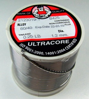
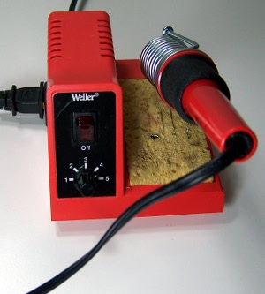
To build the kit, you will need a few common tools for soldering and electronics work. A soldering iron and solder are the most important tools. You can use any soldering iron, although a higher-quality, temperature-controlled adjustable iron will be easier to work with and give higher quality results. Any standard solder for small electronics will do just fine.
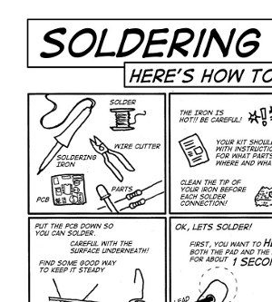
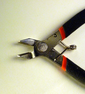
To trim the extra leads on the bottom of the pcb a diagonal pliers will work very well. If you need some instructions about how to solder, there is a great comic available from MightyOhm in many different languages too!
Step 1: Reset pushbutton
Find the four-pin pushbutton switch in the bag of parts. It belongs on the bottom edge of the board next to the W&L logo, and is labeled SW1. It is a rectangular part, so it will only fit into the holes in the board in one of two ways (either way is ok). Once you snap the switch into place, flip the board over and solder the four pins into place. No need to trim these leads as they are short enough already.
Step 2: Ceramic capacitors
Find the three small yellow capacitors. They belong in the pairs of holes labeled “0.1u”. This type of capacitor is not polarized, and can be placed either way. Install the capacitors in the proper holes, then flip the board over. You can bend the wire leads of the capacitors slightly outward to keep them from falling out of the holes.
Solder the wire leads using your solder and iron. Use your diagonal cutters or clippers to cut the wires just past where the solder blob ends. The result should look neatly trimmed, with nice shiny “little volcanoes” of solder surrounding each component lead.
Step 3: L293D motor driver chips
The L293D motor driver chips are used to switch currents larger than the Arduino pins can handle, required by the LEGO NXT motors. The three chips are labeled U1, U2, U3 on the PCB, and you will probably need to bend the pins inward a little bit to get the pins to fit through the holes in the PCB. Be sure to align the notch on the top of each chip with the notch drawn on the PCB, as shown in the image below. Flip the board over and solder down all the pins. No need to trim the leads.
Step 4: 100k resistors
Resistors are unpolarized, so they can be installed either way. First, bend them into a U-shape like a staple, then insert them through the board in the spots labeled “100k”, right next to the L293D chips. You can bend the leads slightly outward on the back side of the PCB to keep them from falling out. Solder down all four connections, then trim the leads.
Step 5: DC power jack
The DC power jack is used to provide power to the motors, and only fits one way in the three holes near the pushbutton you soldered first. Snap the DC jack into the three holes and flip the board over. Use lots of heat and solder to make a solid connection with the PCB, and it helps to angle your soldering iron to make as much contact with the pad and lead as possible (to maximize heat transfer). It still might take 5-10 seconds to heat up the connection before the solder will melt. Try to fill each hole with solder. No need to trim these leads as they are short enough already.
Step 6: Yellow fuse (PTC)
The small yellow fuse is also called a PTC (for Positive Temperature Coefficient, meaning the resistance increases as the temperature increases) and is used to supply the DC input voltage to the Arduino, so it can be powered too. More details about why this part is included are available on the parts list page. The PTC comes attached to a small piece of cardboard called “tape” so you first need to cut both leads at the edge of the cardboard to free the part from the tape. The PTC is not polarized, and should be inserted through the holes of the footprint labeled “F1”, right behind the DC jack.
Step 7: Electrolytic capacitors
There are two types of electrolytic capacitors in the kit (six total), which look like little blue cylinders. They’re labeled, and three are 100 uF, while the other three are 47 uF. They’re polarized, which means they will only function in one orientation. There are many indicators to help you orient it correctly. There is a light strip with minus signs on it, on the can, which indicates the negative terminal. Additionally, one of the leads is longer than the other, which indicates the positive terminal. The board is marked with a + near the positive lead for each capacitor. Install the 47 uF capacitors into the footprints labeled “47u”, and the 100 uF capacitors into the footprints labeled “100u”. Bend the legs outward a bit so the capacitors don’t fall out when you flip the board over. Solder all the leads, and trim the leads.
Step 8: Arduino header pins
The kit includes four strips of head pins, each 36 pins in length. Use pliers to break the long strips into sections of (8,8,8,8,4) + (10,8,5,5,4,4) + (18,18) + (5,5).
Then, insert the long ends into Arduino pin sockets, put PCB over short ends, solder the pins into place from the top side of the board.
Step 9: Custom Sockets
There are 10 custom-made NXT-compatible sockets. They only fit in one way. It helps to first put the metal pins in their holes, and then push the plastic pegs into the strain relief holes. Carefully solder each pin. They don’t need much solder! They definitely don’t need to be trimmed or cut.
Step 10: 4- and 5-pin male headers
Back in step 8 you broke apart the long strips of male header pins into many smaller pieces, including three 4-pin and four 5-pin pieces. The 4-pin headers are used behind motor ports 1, 3, and 5 (labeled “PF1”, “PF3”, and “PF5”), and are used for other DC motors that have the same voltage and current requirement as NXT motors, such as the LEGO Power Functions (PF) motors. The 5-pin headers are used behind the four sensor ports.
To easily solder these headers into the PCB, you can put one of the jumpers on two of the pins as shown in the images below. This will allow you to control the angle of the headers to ensure they are sticking straight out, without burning your fingers on a super-heated pin! We suggest soldering only one pin of each header to start with, then take a look to see if the header pins are flush against the PCB, and sticking out straight. If they need some adjustment, re-melt the single soldered pin, and use the jumper to move the headers into position. When you are happy with the alignment, solder the rest of the pins.
Step 11: Shorting jumpers
To support the different types of LEGO NXT sensors, there is a 5-pin header behind each sensor port. Jumpers are included in the kit to selectively connect pairs of pins on these headers. The default jumper setting is for the pushbutton sensor, and consists of two jumpers placed over pins 2-3 and 4-5.
Step 12: Get started!


