Build Instructions
Looking for shorter instructions? Look no further. We’ve prepared a shorter page with the suggested soldering order.
Step 0: Gather Tools
To build the Video Game Shield, you will need a few common tools for soldering and electronics work. A soldering iron and solder are the most important tools. You can use any soldering iron, although a higher-quality, temperature-controlled adjustable iron will be easier to work with and give higher quality results. Any standard solder for small electronics will do just fine.


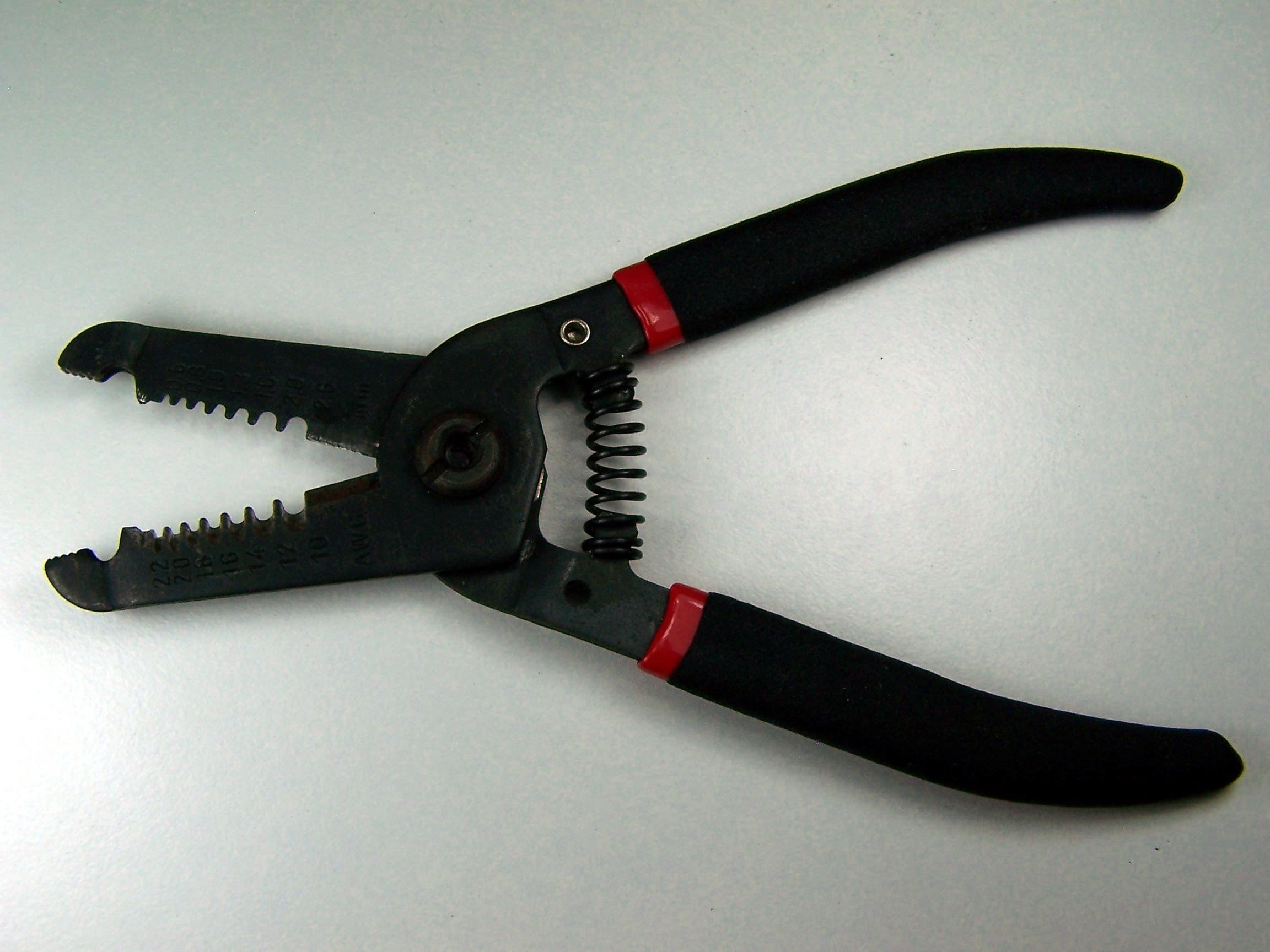
To bend the leads of the push button, you might need a pliers or similar tool. We used the pliers on a wire strippers. To trim the extra leads on the bottom of the pcb a diagonal pliers will work very well.

If you need some additional guidance and instruction on soldering, SparkFun, NASA, and Curious Inventor all have quality soldering tutorials.
Step 1: Part Identification
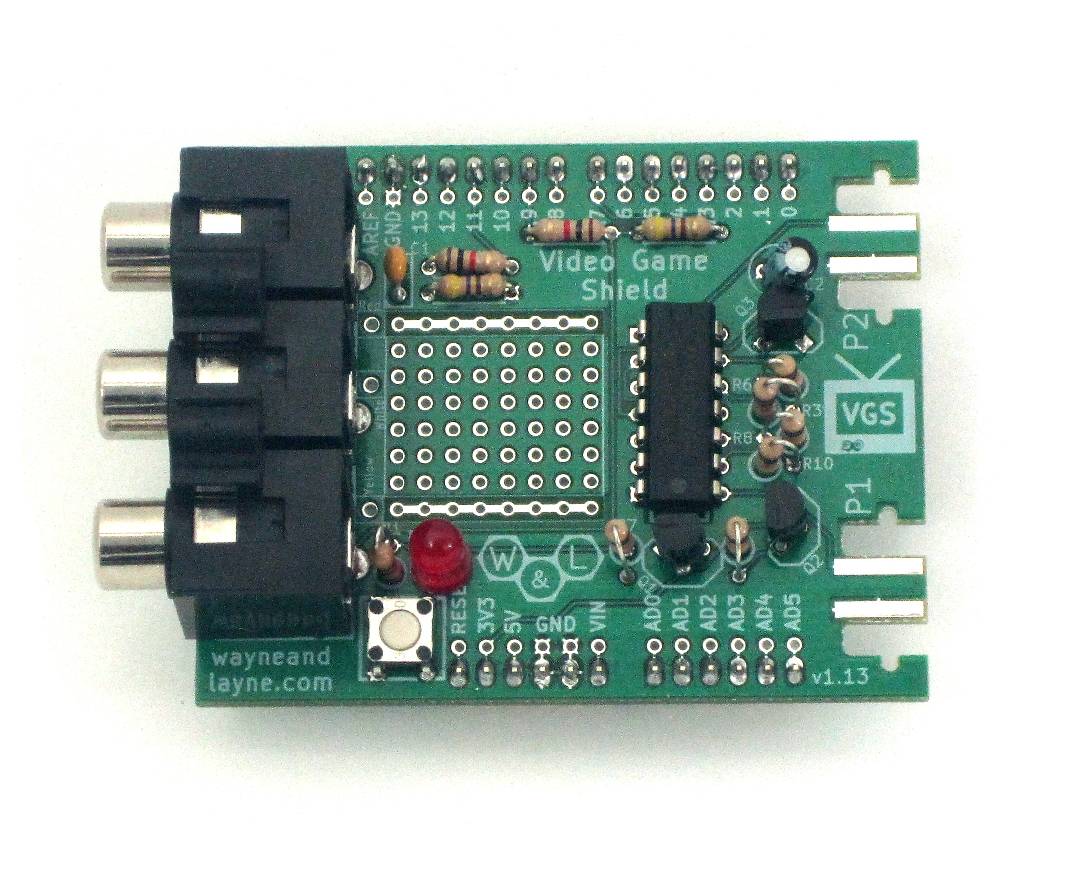
Open the bag of parts, and make sure you have all of the parts listed below. It might be easier to lay them out as shown in the picture. Click to enlarge.

- (1) Video Game Shield PCB
- (2) 1k Ohm resistors
- (3) 470 Ohm resistors
- (6) 10k Ohm resistors
- (1) 0.1 uF ceramic capacitor
- (1) Light Emitting Diode (LED)
- (1) Pushbutton switch
- (3) N-channel MOSFET transistors
- (1) 47 uF electrolytic capacitor
- (1) 4066 switch IC and Chip Socket
- (1) 3x RCA jack
- (1) Pin Headers
This kit is easy to solder, and shouldn’t take too long. We’ll start with the easiest parts, and work our way to the more complicated parts. The general plan is to solder in the shortest parts first, and the tallest parts last.
Some parts are polarized, and have to go in the board a certain way, but also some parts are not polarized. In the steps to follow, if a part is polarized, we will mention which way it must be installed. The PCB is also be marked to identify the polarization.
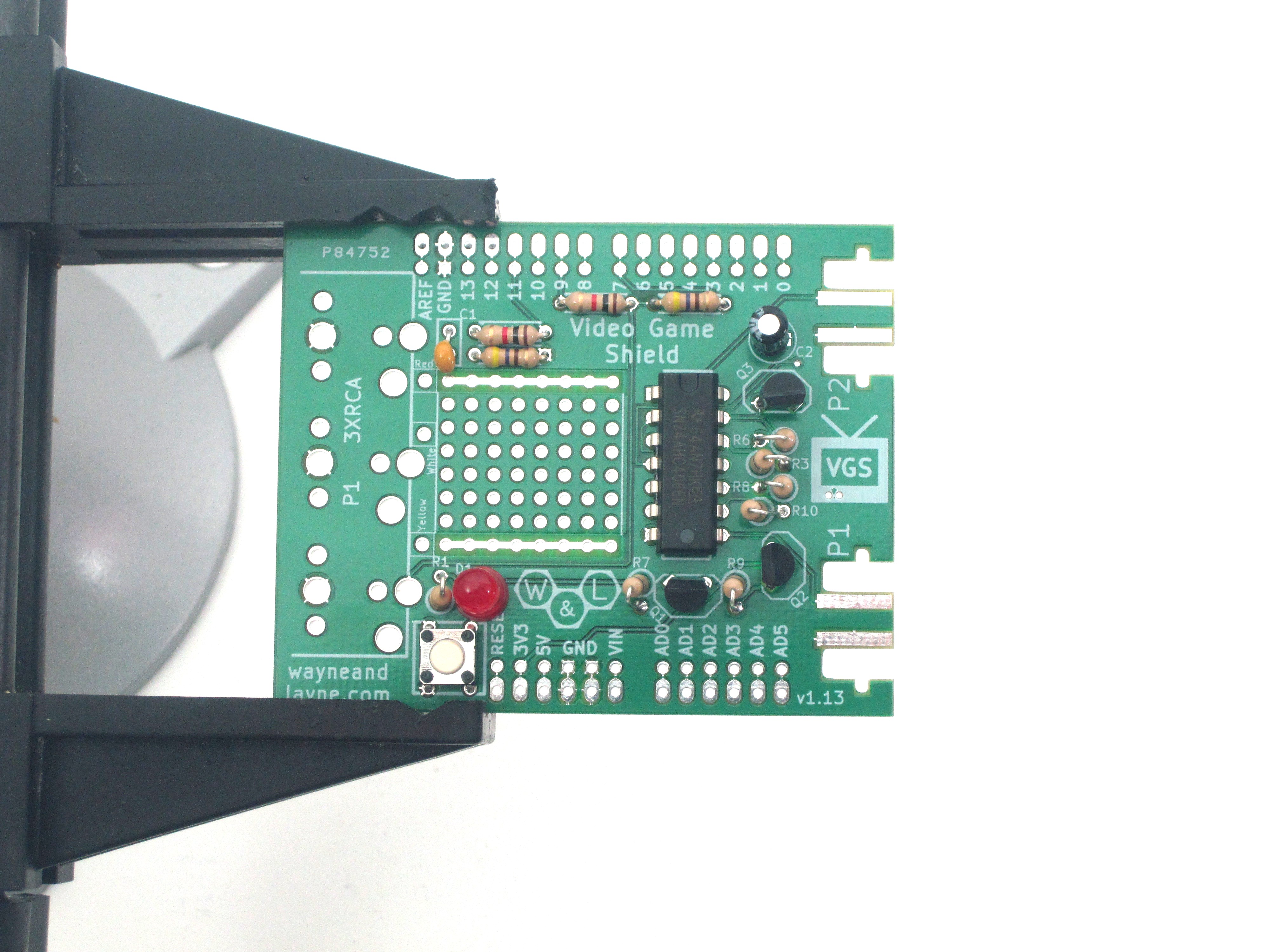
Step 2: 1k ohm resistors
Resistors are easy to solder, so start with these 1k ohm resistors. They are marked with Brown-Black-Red colored bands. Bend the leads so the resistors fit into the marked locations in the upper-left side of the board. Resistors are not polarized, so they don’t have to go in a certain way. To solder things with long legs like this, you can turn the board over and bend the legs a little bit, so the component doesn’t fall out while the board is upside-down.


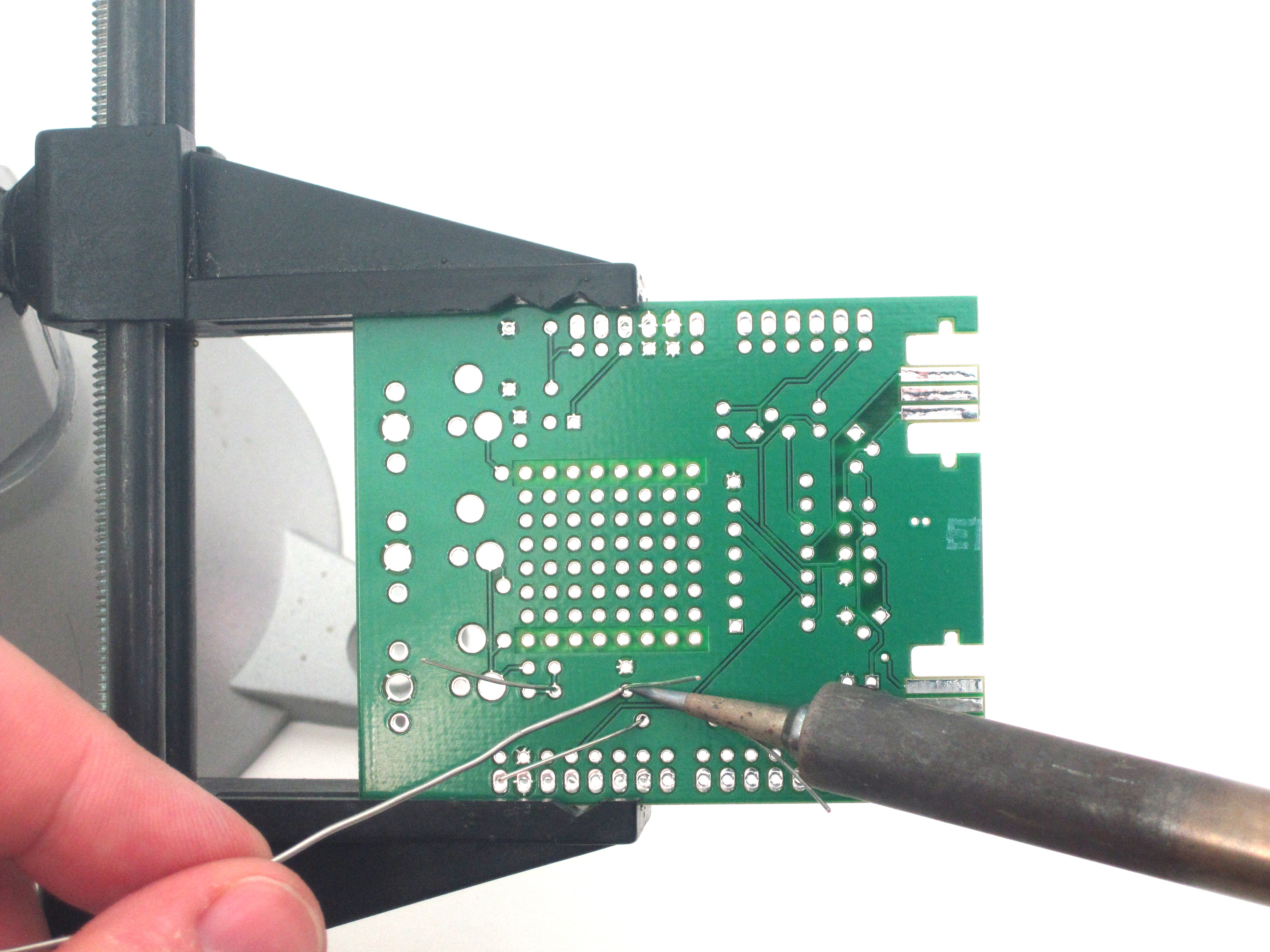
Use your soldering iron to heat up one leg of the first resistor and the ring around the hole at the same time. Push a little bit of solder on the ring. The solder should melt and flow around the hole. If you’re having trouble, make sure the tip of your iron is tinned and shiny. Remember to heat up the pad and the pin, and you don’t need to apply a lot of solder. Don’t try to use the iron like a paintbrush. Use the diagonal clippers to trim the legs of the resistors, down to just above the solder joints.

Step 3: 470 ohm resistors
Take one of the three 470 ohm resistors and bend down one lead back on itself, as shown in the first photo. Turn the board back over and put this resistor in its proper location, near the bottom-left part of the board. Again, resistors are not polarized, so direction doesn’t matter.


Add the other two 470 ohm resistors near the first two 1k ohm resistors.


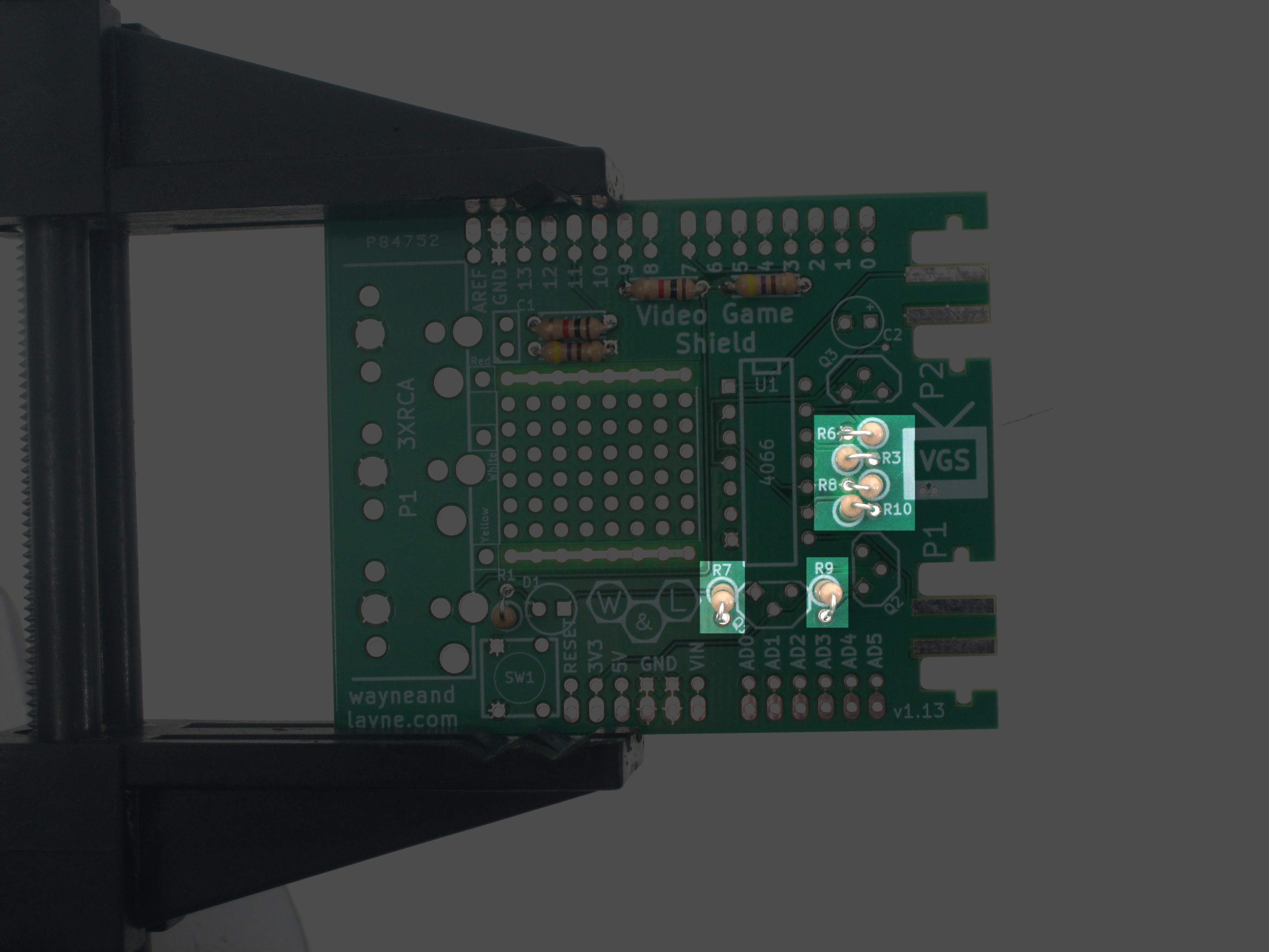
Step 4: Add 10k resistors
There are six 10k resistors to add, on the right-hand side of the board. They are all in the ‘vertical’ orientation, so for each resistor, bend over one lead, like in the previous step. Put the resistors through their holes, flip the board over, and solder them in. Trim the leads as normal.
Step 5: Capacitors
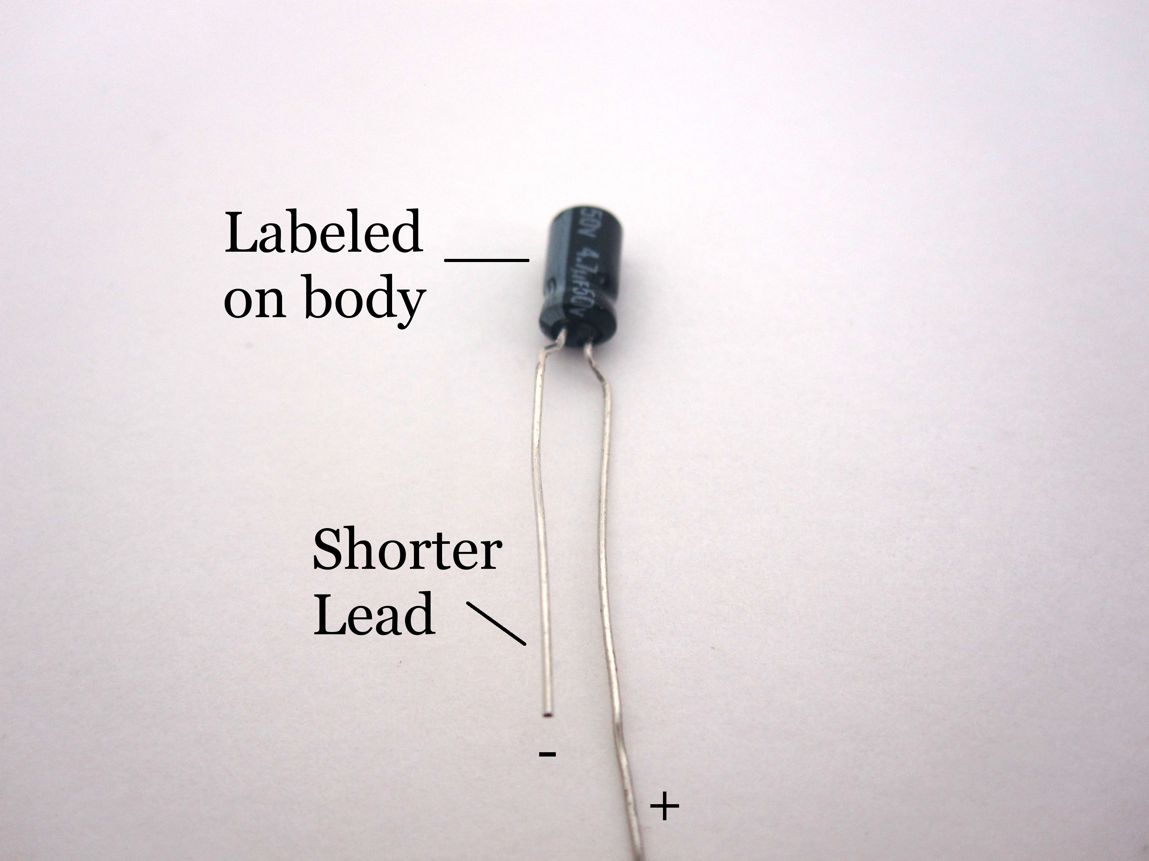
There are two capacitors to add in this step. The first is a small yellow ceramic capactor. It is not polarized, and belongs in the upper-left part of the board next to two resistors. The electrolytic capacitor looks like a small blue and silver cylinder. This type of capacitor is polarized, with a positive (+) leg and negative (-) leg, and must be inserted properly. The negative leg is usually labeled on the side of the capacitor itself, and is shorter than the positive leg. The positive leg is labeled on the board with a small + sign.

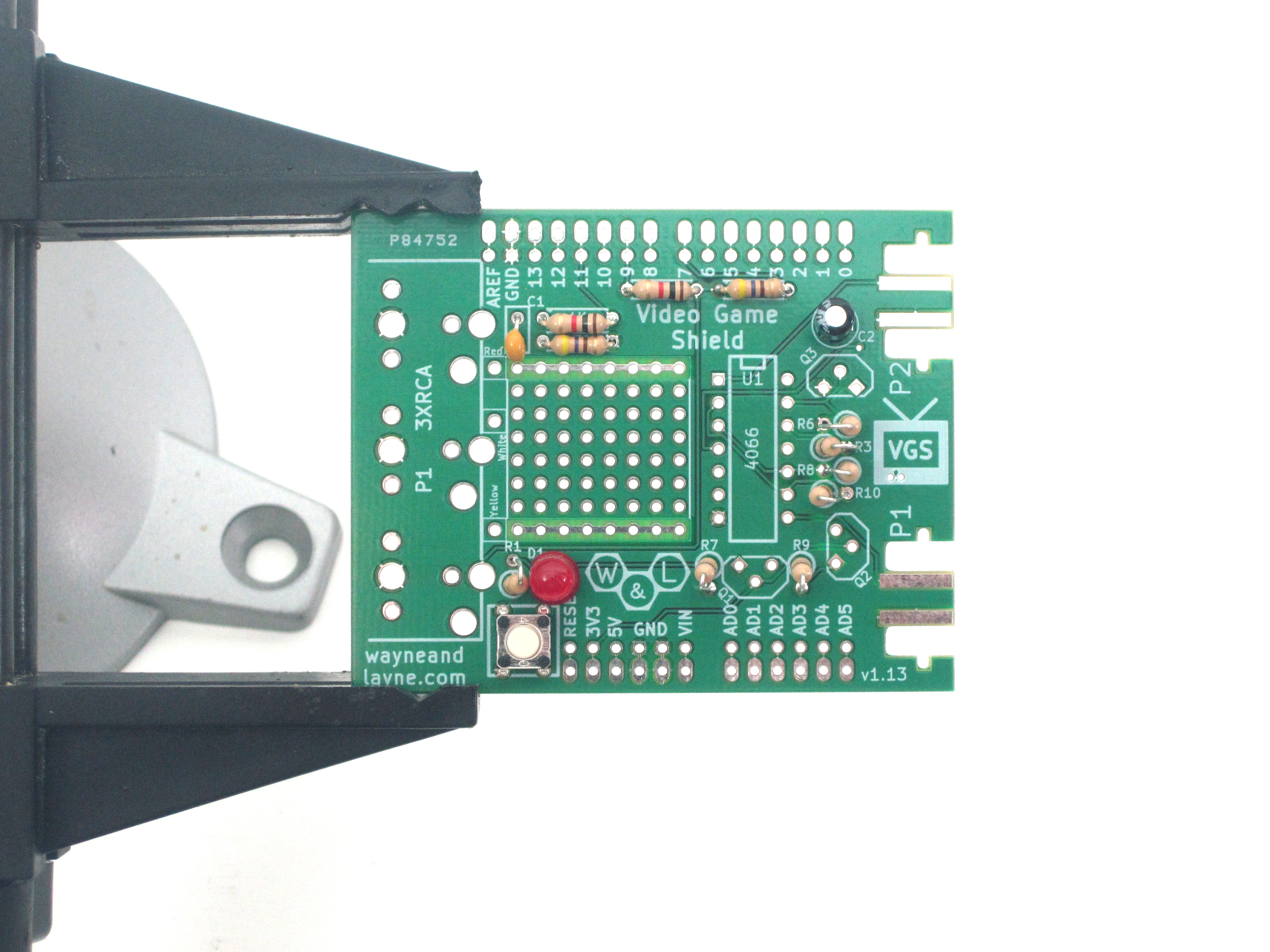
Step 6: Light Emitting Diode (LED)
Insert and solder the LED, labeled D1 on the PCB. It is polarized, so be sure to put the longer (positive) lead in the hole with the square outline, on the right side of the part. Bend the leads so it doesn’t fall out, then solder and clip the leads.


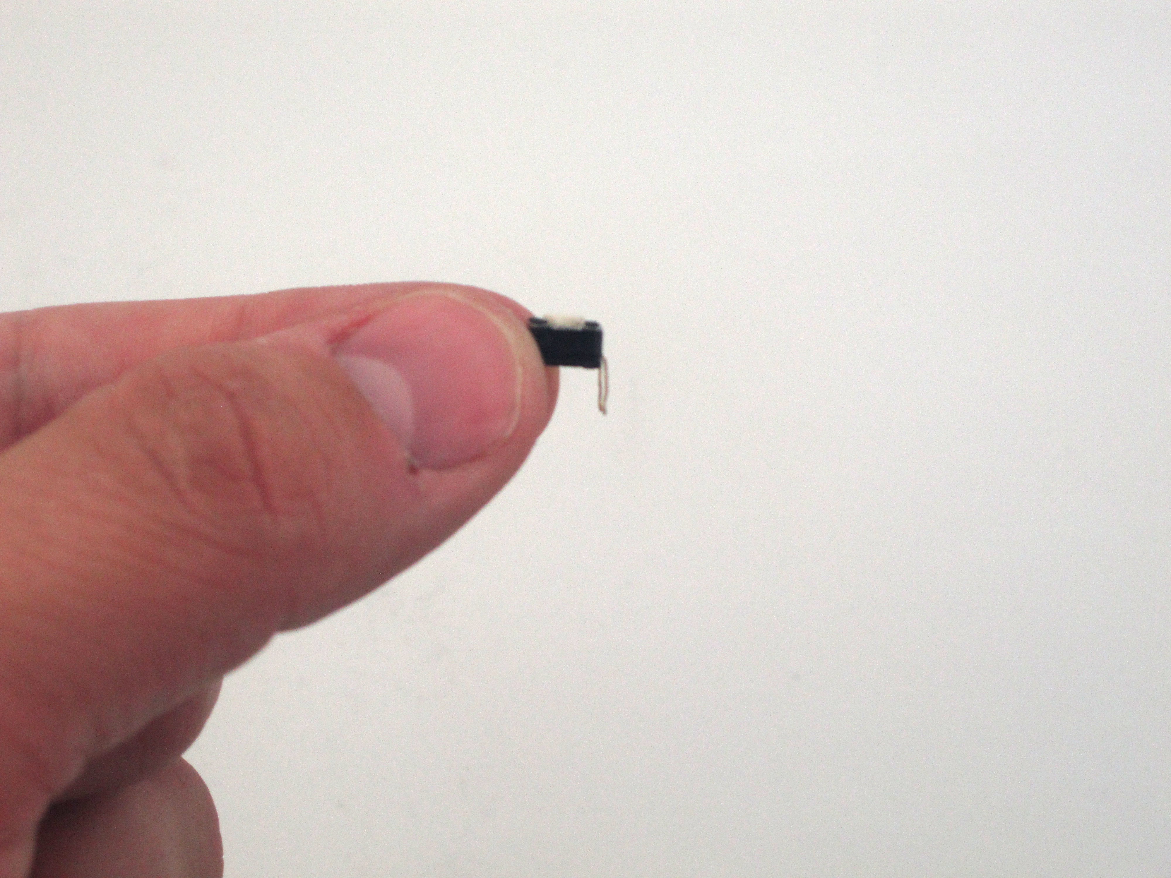
Step 7: Reset button
The reset button is used to reset the Arduino, since the Video Game Shield obstructs the Arduino’s own reset button. It might be easier to put the button in place if you first straighten the leads with a pliers. The button belongs just below the LED from the previous step.
Step 8: Mosfet transistors
There are three Mosfet transistors in the Video Game Shield, used to help switch between the two Nunchucks. These are three-pin devices, and are polarized. Each one has a flat side, which should be aligned with the flat side of the drawing on the board. Bend the leads slightly so they fit into the holes. Solder them in and trim the leads. Now would be a good time to ensure that you have trimmed all the leads properly. Take a look back over your work and make sure everything looks great!


Step 9: 4066 switch IC and Chip Socket
The 4066 switch IC lets us switch back and forth between the two nunchucks. To get the chip to fit in the board, you first need to slowly and carefully bend the leads inward, slightly. One easy way to do this is to evenly push the side against the table surface, as shown in the first image below. The leads should be nearly vertical after you do this.
Note: Your kit may have included a chip socket (only the first batch of kits shipped without a socket). This socket is used to protect the chip from the high temperatures of the soldering process, and enables you to remove the chip if needed for troubleshooting or replacement. To solder the socket in, simple align it with the notch on the PCB. Follow the same soldering steps below. Bend the leads of the IC as indicated, and push it into the socket when you’re finished soldering it.

Please the chip on the board, making sure to follow the polarity markings. The chip has an indentation at one end to indicate pin 1, and it should line up with the similar indentation marking on the circuit board. To keep the chip from falling out, you can bend two of the corner pins.

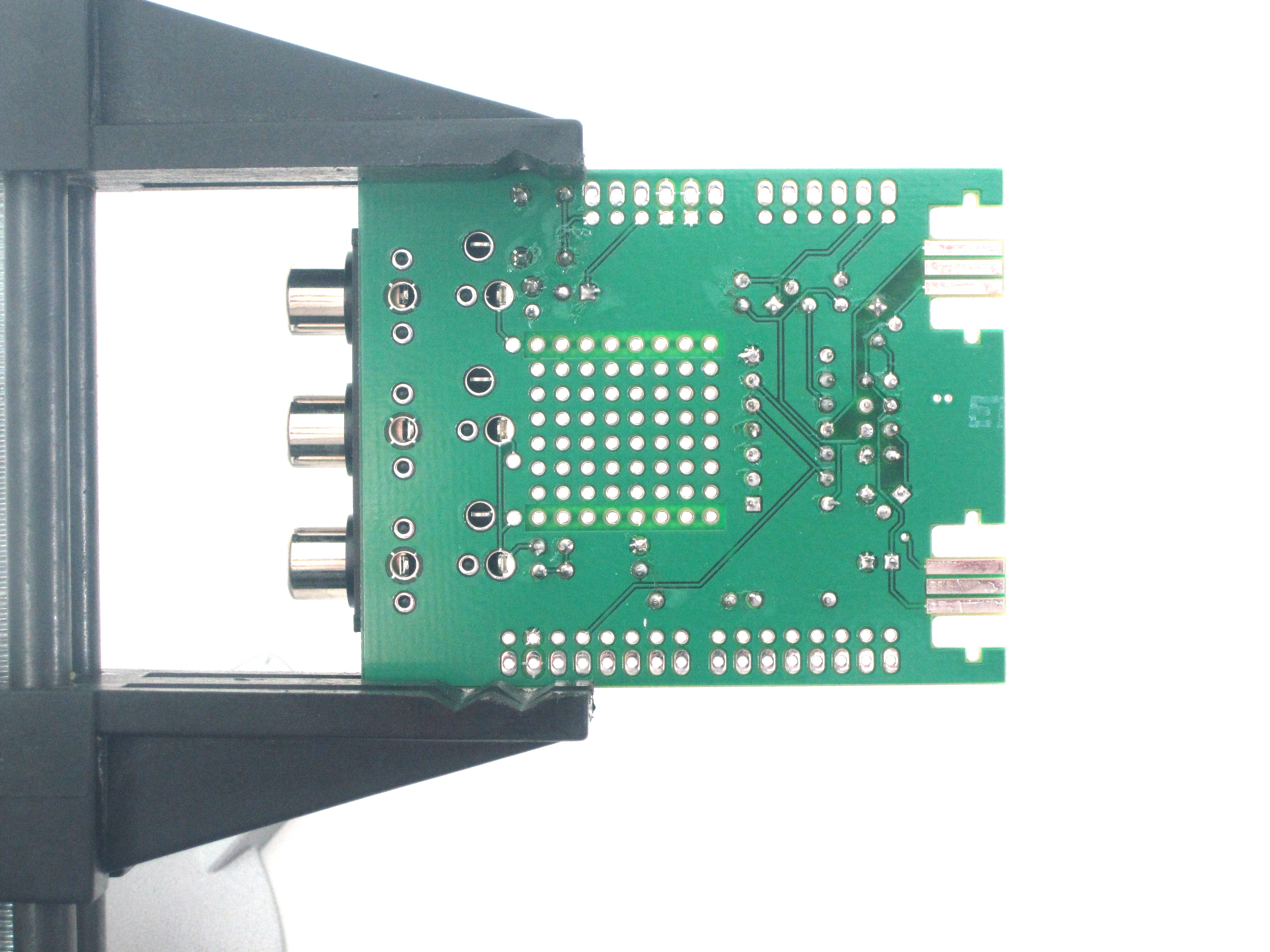
Step 10: RCA jacks
The three RCA jacks provide the audio and video signal connections with your television. Place the jack in place and push it down. There are a lot of pins here, so it might require a little force to get it in place. The fit is tight, but that\s the way we want it. The big holes might require more solder than other parts, but make sure to heal the whole pad and pin, and you should be fine.

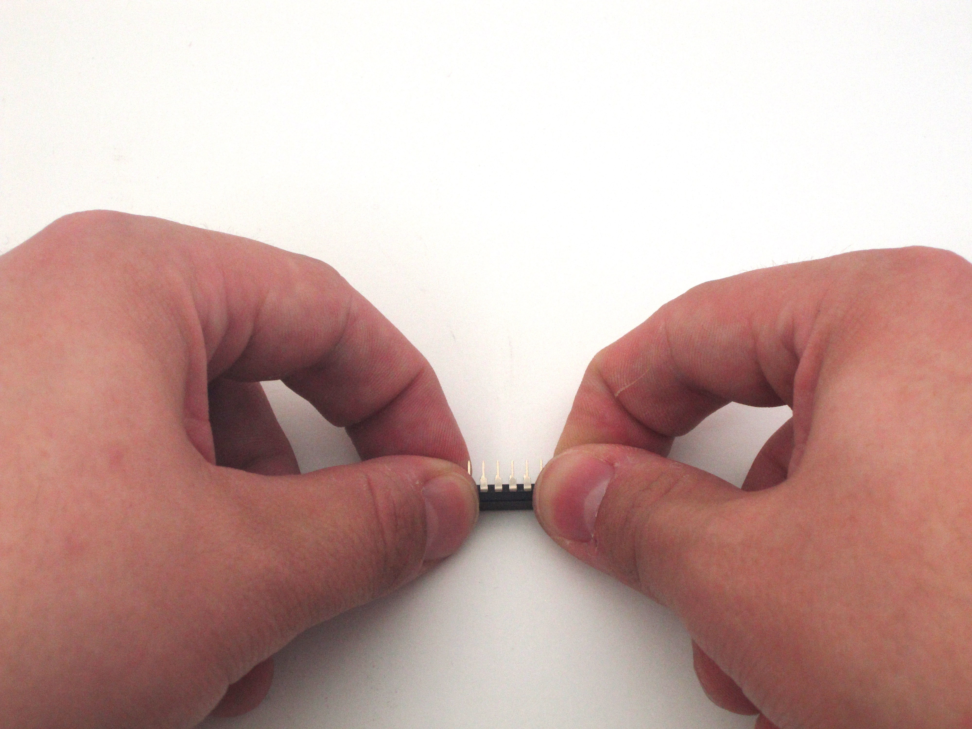
Step 11: Shield header pins
You should have received a long row of “breakaway” header pins. You can insert one end into each section of your Arduino’s pin sockets, and then break away the extra pins. When you’ve added all the header pins into your Arduino’s sockets, place the Video Game Shield on top of the header pins, and solder it down. This process ensures that the pins are aligned properly with an Arduino.


Step 12:
Give the completed board a final look over, checking for loose solder connections or shorted pads. Congratulations! You’re now the proud owner of a new Video Game Shield. Hook it up to your TV and give it a try!