Build the Bricktronics Shield
We have detailed step-by-step instructions with photos, as well as a quick-build list.
Quick build instructions:
- Push Button – SW1 – Not polarized
- 0.1uF Ceramic Capacitors – C1 and C3 (or “0.1u”) – Not polarized
- DPDT Slide Switch – SW2 – Not polarized
- MCP23017 I/O Expander chip and socket – U1 – Solder socket into PCB, then push chip into socket – Polarized: Match notch on chip/socket with notch on PCB artwork
- L293D Motor Driver Chip – U2 – No socket for this chip – Polarized: Match notch on chip with notch on PCB artwork
- 100k resistors – R6 and R7 (or “100k”) – Not polarized
- 1k resistors – Marked “1k” on PCB – Not polarized
- 47uF Electrolytic Capacitor – C2 (or “47u”) – Polarized: Long lead is positive (marked on board), short lead is negative
- 100uF Electrolytic Capacitor – C4 (or “100u”) – Polarized: Long lead is positive (marked on board), short lead is negative
- NXT-compatible sockets – Motor and Sensor ports on left and right edges of PCB – Only fits one way
- TIP120 transistors – Q4 and Q5 – Polarized: Align tall vertical part of TIP120 with marked edge on PCB artwork. Letters on TIP120 should face towards the motor sockets.
- Female headers, 4-pin – EXT1 and EXT2 – Not polarized, but ensure they are flush against PCB (Optional, used in Make: Lego and Arduino Projects)
- Male headers, 5-pin – Just behind sensor ports 3 and 4 – Not polarized, but ensure they are flush against PCB
- Male headers, 4-pin – Just behind both motor ports (for PF motors) – Not polarized, but ensure they are flush against PCB (Optional, used in Make: Lego and Arduino Projects)
- Breakaway male headers – Break the headers into pieces of size 6, 8, 8, and 10 pins (for a newer-style Arduino like the Uno R3 or the Leonardo) or sizes 6, 6, 8, and 8 for an older style Arduino. For the best alignment, stick the headers into an Arduino, then slide the shield over the header pins’ short side. Solder the pins into place from the top side of the board.
- Diodes – The diodes help protect motors or other devices you might control using the TIP120 transistors.
- Stacking Female Headers (optional) – These can help make it easier to temporarily connect a prototyping wire to an Arduino pin.
These are the building instructions for the Bricktronics Shield kit.
Step 0: Gather Tools
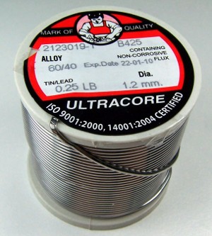
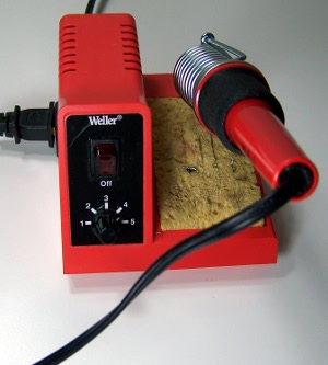
To build the kit, you will need a few common tools for soldering and electronics work. A soldering iron and solder are the most important tools. You can use any soldering iron, although a higher-quality, temperature-controlled adjustable iron will be easier to work with and give higher quality results. Any standard solder for small electronics will do just fine.
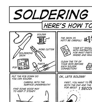
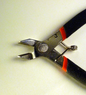
To trim the extra leads on the bottom of the pcb a diagonal pliers will work very well. If you need some instructions about how to solder, there is a great comic available from MightyOhm in many different languages too!
Part Identification
Open the bag of parts, and make sure you have all of the parts listed below. It might be easier to lay them out as shown in the picture. Click to enlarge.
- (1) Bricktronics Shield Printed Circuit Board – PCB
- (1) Push Button – SW1
- (2) 0.1uF Ceramic Capacitors – C1, C3
- (1) DPDT Slide Switch – SW2
- (1) MCP23017 I/O Expander Chip and Socket – U1
- (1) L293D Motor Driver Chip – U2
- (2) 100 kΩ resistors – R6, R7
- (2) 1 kΩ Resistors
- (1 each) 47uF and 100uF Electrolytic Capacitors
- (6) NXT-compatible Sockets
- (2) TIP120 Transistors – Q4, Q5
- (2) Female headers, 4 pins
- (4) Shorting Jumpers
- (1) Breakaway male headers
- (2) 1N4001 Protection Diodes
- (4) Stacking Female Headers (optional)
This kit is easy to solder, and shouldn’t take too long. We’ll start with the easiest parts, and work our way to the more complicated parts. The general plan is to solder in the shortest parts first, and the tallest parts last.
Some parts are polarized, and have to go in the board a certain way, but also some parts are not polarized. In the steps to follow, if a part is polarized, we will mention which way it must be installed. The PCB is also marked to identify the polarization.
Step 1: Reset pushbutton
Find the four-pin pushbutton switch in the bag of parts. It belongs on the bottom edge of the board below the Motor 2 port, and is labeled SW1. It is a rectangular part, so it will only fit into the holes in the board in one of two ways (either way is ok). Once you snap the switch into place, flip the board over and solder the four pins into place. No need to trim these leads as they are short enough already.
Step 2: Ceramic capacitors
Find the two small yellow capacitors. They belong in the pairs of holes labeled C1 and C3 (newer boards label it as “0.1u”). This type of capacitor is not polarized, and can be placed either way. Install the capacitors in the proper holes, then flip the board over. You can bend the wire leads of the capacitors slightly outward to keep them from falling out of the holes.
Solder the four connections using your solder and iron. Use your diagonal cutters or clippers to cut the wires just past where the solder blob ends. The result should look neatly trimmed, with nice shiny “little volcanoes” of solder surrounding each component lead.
Step 3: DPDT slide switch
This little slide switch lets you select the proper source of the I2C signals for the I/O Expander chip. The switch is not polarized, and can be installed in either orientation. Insert the switch, then flip the board over and solder it in on the back side. No need to trim the leads as they are short enough already.
Step 4: MCP23017 I/O Expander chip socket
To enable replacement (and also protect from damage) we have a socket for the I/O Expander chip. Align the notch on the socket with the notch on the PCB outline for U1 (near the Bricktronics B logo). You can bend pins in the corners to keep the socket from falling out of the board. Flip the board over and solder down all 28 pins. No need to trim the leads.
Step 5: L293D motor driver chip
One downside about using a chip socket is that the chip is further from the PCB. This is generally not an issue, except when your chip is dissipating a lot of power as heat, like our L293D chip might. We don’t use a chip socket for this chip, and just solder it directly to the PCB. You will probably need to bend the pins inward a little bit to get the pins to fit through the holes in the PCB. Be sure to align the notch or dot on the top of the chip with the notch drawn on the PCB. Flip the board over and solder down all the pins. No need to trim the leads.
Step 6: 100k resistors
Resistors are unpolarized, so they can be installed either way. First, bend them into a U-shape like a staple, then insert them through the board in the spots labeled R6 and R7 (newer boards label them as “100k”), right next to the L293D chip
You can bend the leads slightly outward on the back side of the PCB to keep them from falling out. Solder down all four connections, then trim the leads.
Step 7: 5-pin male headers
The breakaway male headers come on a strip, and need to be broken apart into various specific lengths. For this step, you will need 2 pieces that are 5 pins long. You can use a pair of pliers to help break the pins, but you can also use your fingers. Install the two pieces into the holes in front of Sensor Port 3 and Sensor Port 4. It may help to do these one at a time–it won’t affect the build either way.
You can hold the pins into the board by holding one end down, and soldering one pin on the other end. Be careful not to touch the pin that is being soldered–it will be hot! Some people use a rubber band instead. Solder the rest of the pins.
Step 8: 1k resistors
Resistors are unpolarized, so they can be installed either way. First, bend them into a U-shape like a staple like you did with the other resistors, then insert the 1k resistors through the board in the spots labeled “1k”.
You can bend the leads slightly outward on the back side of the PCB to keep them from falling out. Solder down all four connections, then trim the leads.
Step 9: Electrolytic capacitors
There are two electrolytic capacitors in the kit, which look like little cylinders, usually blue or gray in color. They’re labeled, and one is 100 uF, while the other is 47 uF. They’re polarized, which means they will only function in one orientation. There are many indicators to help you orient it correctly. There is a light strip with minus signs on it, on the can. This indicates the negative terminal. One of the leads is longer than the other. The longer lead is positive. The board is marked with a + near the positive lead for each capacitor. Install the 47 uF into C2, and the 100 uF into C4 (on newer revisions of the PCB, the two capacitors are labeled with their values instead of C2/C4). Bend the legs out so the capacitors don’t fall out. Solder them, and trim the leads.
Step 10: Custom Sockets
There are 6 custom-made sockets. They only fit in one way. It helps to first put the metal pins in the holes, and then snap the plastic pegs into the strain relief holes.
Carefully solder each pin. They don’t need much solder! They definitely don’t need to be trimmed or cut!
Step 11: Install the MCP23017 IO expander
The 28 pin IO expander is next! Carefully bend the legs straight, like you did with the L293D, and line up the notch on the top of the chip with the notch on the socket (and the board, but you already did that when you soldered the socket in.)
Step 12: Install the TIP120s
There are two TIP120 Darlington transistors. They’re used on this shield for “supplemental capabilities” like driving 12V LED modules or non-LEGO motors. They will only work in one orientation, so line up the back heatsink with the thick white line on the PCB drawing. Make sure it matches the photo. The transistors won’t go in all the way, but make sure they’re in as far as they go, and then bend the legs on the back so they don’t fall out.
Solder them and trim the legs. Note about the included diodes: The diodes are included in case you are using the TIP120 transistors to drive a non-LEGO motor.
Step 13: Install the 4 pin female headers
To make it easier to use the TIP120s without soldering, we’ve included female headers. They can go in either way, and they go into the spots labeled EXT1 and EXT2.
Tack solder them like you did the male headers by Sensors 3 and 4, and then solder the rest of the pins. There’s no need to trim the legs.
Step 14: Install the 4 pin male headers
If you want to plug in other DC motors that have the same voltage and current requirement as NXT motors, you can plug them into these ports.
The male headers come on a strip, and need to be broken apart into various specific lengths. For this step, you will need 2 pieces that are 4 pins long. You can use a pair of pliers to help break the pins, but you can also use your fingers.
They can go in either way, and they go into the spots labeled PF1 and PF2.
You can hold the pins into the board by holding one end down, and soldering one pin on the other end. Be careful not to touch the pin that is being soldered–it will be hot! Some people use a rubber band.
Step 15: Install the Arduino header pins
Many Arduino shields can have special header pins that allow you to stack multiple shields together, but the NXT sockets on the Bricktronics Shield are too tall to permit stacking another Arduino shield on top. The Bricktronics Shield comes with standard breakaway male headers for connecting it to the Arduino.
Depending upon if you have an older or newer Arduino, you may want to use one of two different header configurations. The newer-style (“Rev 3”) use a 10, two 8, and a 6 pin header, while the older style use two 8 and two 6 pin headers. It makes no difference to the Bricktronics Shield build. We suggest using the newer-style 10-8-8-6 pins unless you work primarily with older Arduino boards.
To use the male headers, one trick is to break off the male headers into appropriate lengths, and place them into an Arduino. Install the assembled PCB on top of the headers, and solder the board to the headers. It really helps with alignment to do it this way.
Step 16: Diodes
The two diodes are included in case you are using the TIP120 transistors to drive a non-LEGO device, such as an external motor or solenoid. When a motor is running, the electrical current flowing through the motor’s coils build up a kind of electrical “momentum” in the coils’ magnetic fields. When the TIP120 stops conducting electricity through the motor’s coils, the magnetic fields collapse, releasing their stored energy as a current pulse. Since the TIP120 has stopped conducting, this current pulse has nowhere to go, and can build up a large voltage spike, which could damage the TIP120 or other components. To safely deal with this current pulse, you can use a diode (which acts here like a one-way gate for electricity) to redirect the current pulse back into the motor coils, where it can safely dissipate.
For version 1.03 of the Bricktronics Shield PCB, we made a mistake in how these diodes are connected on the PCB. If you want to use the TIP120 with an external device, use one of the included diodes to connect across the leads of your motor or other device, “pointing up” so that it does not conduct when the external device is powered. For version 1.04 of the Bricktronics Shield PCB, we have corrected the mistake and you can install the diodes in the locations labeled D1 and D2.
Step 17: Get started!


