


Nice drawings of the Arduino UNO and Mega 2560
If you’re looking to make your own shield for the Arduino platform, you’ll definitely need to know where all the pins and holes are located on the Arduino. After doing a quick search, I was unable to find an accurate technical drawing of the new Arduino UNO and Arduino Mega 2560.
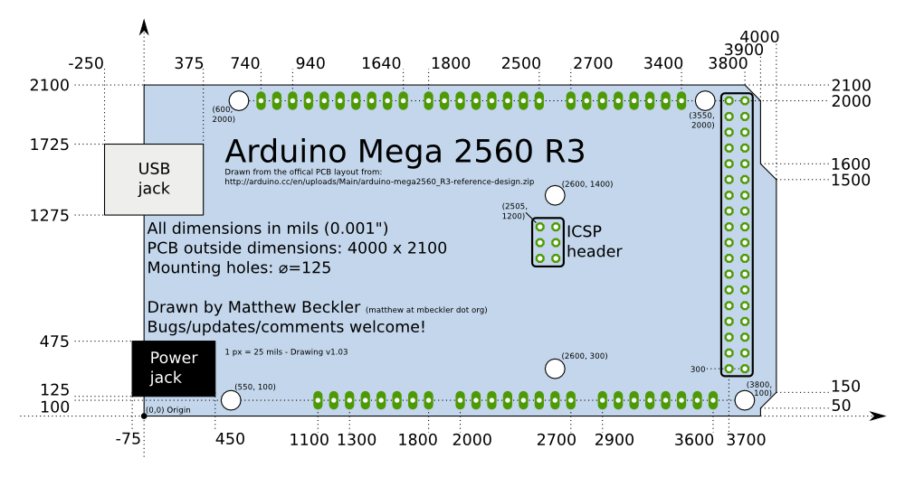
Using the PCB design files available at the Arduino hardware website, I created a detailed technical drawing of both the Uno and Mega 2560. The drawings are available in vector-based SVG format, but low-resolution PNG files are shown below (click for larger versions). All drawings are released into the public domain, but let us know if you find any mistakes or have any suggestions or updates.

(If you just click on the SVG file link, the image will probably show up very small in your browser window. If you save the file and instead open it with an SVG editor such as Illustrator or the very awesome, Free and Open Source Inkscape vector graphics editor, you will be able to enlarge the image. The image is so “small” because I scaled the image to be 1 pixel = 25 mil, to make it easier and more accurate to draw.)
Update 1: The drawings have been updated to be more consistent, and with absolute coordinates. Thanks to those who wrote in with suggestions.
Update 2: The UNO drawing has been updated to fix some incorrect numbers on the lower-right corner detail, and fixed the location of the ICSP header to match exactly the goofy position it has on the real PCB design. Many thanks to Ryan Mulligan for his comments below with the bug fixes.
Update 3: The UNO and Mega 2560 drawings have been updated to match the newest rev3 PCBs. They added two extra pins each to the left edge of the top and bottom left header blocks.
Update 4: I have added very high-resolution PNG renderings of these two SVG drawings. Arduino UNO 5000×3515 — Arduino Mega 2560 5000×2642
Update 5: Arduino fixed the location of the ICSP header on the Uno layout to match the location on the Mega (2505x 1200). Thanks to Neal G. for the heads-up.
You guys still use Imperial measures?
Mils are a really weird measure. They are basically saying “we know Imperal is stupid and hard to calculate with so we are having a base 10 metric measurement, only we use the same metric SI units as the rest of the world so decided to make our own.”
I based my drawings right from the Eagle PCB design files, which were drawn up in mils. I know I can switch Eagle to use metric units, but the numbers aren’t always cleanly converted, and it seems that the board was designed in mils.
Hello, Layne.
I noticed some errors in the drawing you have posted here. I updated the SVG file to fix them. The biggest problem is the board outline in the bottom right is off by 50 mils, but all of the angled edges of the board were off.
Updated SVG file:
http://goo.gl/jppoj
Regards
Ryan Mulligan
Hello.
I’m sorry, my last link did not work. I thought Amazon Cloud Drive would be able to handle sharing, I guess not. Here it is in Dropbox, which handled sharing very nicely:
http://dl.dropbox.com/u/25319396/arduino%20drawing.svg
– Ryan
Ryan, Thanks much for the bug fixes, I have incorporated your changes to my drawings, and re-posted them to this page. I also emailed the Arduino developers mailing list about that very strange positioning of the ICSP header on the UNO. I presume they want them to match between all their board designs?
Thank you! I’ve been looking for the mechanical info on the Uno – exactly what I needed.
Hello Lane!
Can you please export this drawing to DWG format? I am not sure what software to use for svg, and if I can convert it myself with a free software.
Thanks!
Hi Gaganodi, you can use the very good free and open source software called Inkscape – http://inkscape.org/ (they have versions for Windows, OSX, and Linux) – to convert the above SVG files into a number of different formats, possibly including DWG. Good luck!
Hi,
has anybody a drawing of the side view with the USB and power connector?
Thanks!
I am a student, my work will need this website images, mind if I use the Nice drawings of the Arduino UNO and Mega 2560 figure?
Full DXF drawings for arduino uno and mega can also be found here:
http://petrkout.com/electronics/arduino-uno-and-mega-dxf-drawings/
Thank you!! very useful
Thanks so much for your work.
Thanks for this, used it to create a base board for a chipKit Max32, this came in very handy.
What is the actual size of the full svg drawing in cm, please? I’d like to print it out from Inkscape and have it scale accurately.
Hi Dusty,
I designed the SVG files to have each pixel =25 mil (25 thousandths of an inch) = 0.635 mm.
UNO
SVG is 170.45 pixels wide by 119.81 pixels tall
= 108.23575 mm wide by 76.07935 mm tall
Mega 2560
SVG is 229.01 pixels wide by 121.02 pixels tall
= 145.42135 mm wide by 76.8477 mm tall
Hope that helps!
Interpretation, in a whiney voice, – “Oh me oh my. You have given me hour and days of work for free and it is imperial, not metric. I cannot forgive you! Who do you think you are? I want my money back. And please don’t forget the shipping costs.”
As for me, thank you very, very much. I am using this information and appreciate it very much! Should I want to convert to any other standard I will do that on my time, but since I’m in the US and since all the connectors, etc are in tenths (ten thousanths of an inch for those imperially challenged) are in thou I appreciated your presentation much more.
Please don’t convert.
David
Nice drawings, but what are the units for the numbers on the drawing? (I don’t see it labeled anywhere or in the text??) Thanks!
Hi Matt, all units in the diagrams are in mils (thousandths of an inch), to match the original board design units. The SVG file itself has 1 pixel = 25 mil.
I have a base board on which Arduino Yun board is going to be placed. So i had a plan to have male connectors on base board so that we can easily place Arduino Yun on Base board.
I need complete dimensions of Arduino Yun Board including female connectors on it.
So, could anyone please suggest me to get the same?
Hi Ajit, I would suggest downloading the Arduino Yun PCB design from the Arduino website. Then install Eagle CAD software free version and open the Yun design there. That is how I was able to find the exact coordinate locations of the features of the Arduino Uno and Mega 2560. Good luck, let us know if you end up creating a comparable diagram of the dimensions!
Can Anyone can upload or send me arduino YUN Board File like same as upper.
i need mechanical file .
Please Help .
Hi DG, I would suggest downloading the Arduino Yun PCB design from the Arduino website. Then install Eagle CAD software free version and open the Yun design there. That is how I was able to find the exact coordinate locations of the features of the Arduino Uno and Mega 2560. Good luck, let us know if you end up creating a comparable diagram of the dimensions!
Hello,
you have to change the 1px = 25 mils to 1px = 25,4 mils because the mega board is 101,6 mm and not 100.
To hello@hello.de, thanks for your comment, but I think you are mistaken. I have just re-downloaded the Arduino Mega 2560 circuit board Eagle PCB design, and it shows that the board is 4000 mils wide (101.6 mm) by 2100 mils tall (53.34 mm). The light-blue object in the SVG file for the Mega 2560 (not counting the black border of the object) is 160 SVG px wide and 84 SVG px tall, which (when multiplied by 25 mil/px) is 4000 mil by 2100 mil.
Hello,
How can I use this svg image in my eagle pcb board?How to obtain its footprints into eagle to connect with other components?
Hi Gaurav Singh, I don’t know much about Eagle, but I would suggest downloading the open-source Arduino design files, and using those directly to design you Arduino footprint. Are you looking to design an Arduino shield? If so, it should be very quick to use this drawing to design a schematic symbol and corresponding PCB footprint that contains the holes for the shield header pins. Good luck!
Thank you so very much! You saved me hours of work.
Terrific resource, thanks for making it available to the world!
Thanks for the awesome measurements! I’m using Easyeda to design a rather large shield for the Arduino Mega for my home automation. The very large shield will plug into the Mega 2560, and contain a lot more Analogs, inputs and outputs, with optocouplers, and some relays for the outputs. I’m new to Easyeda, and maybe there’s another way, but this enabled me to place the headers for the Arduino Mega perfectly (well… I hope). I double checked the holes in the headers and the x,y coordinates verified I have them placed correctly.